
Understanding Gear Module
The Core Dimensional Benchmark of Mechanical Transmission Systems
In precision machinery and intelligent manufacturing, gear transmission acts as the core carrier for power output, speed regulation and motion synchronization. Among all gear design parameters, module (m) is the most fundamental and decisive dimensional benchmark. It directly dominates gear tooth geometry, structural stiffness, meshing accuracy and standardization compatibility, supporting the full lifecycle of mechanical R&D, transmission optimization, precision manufacturing and equipment maintenance.
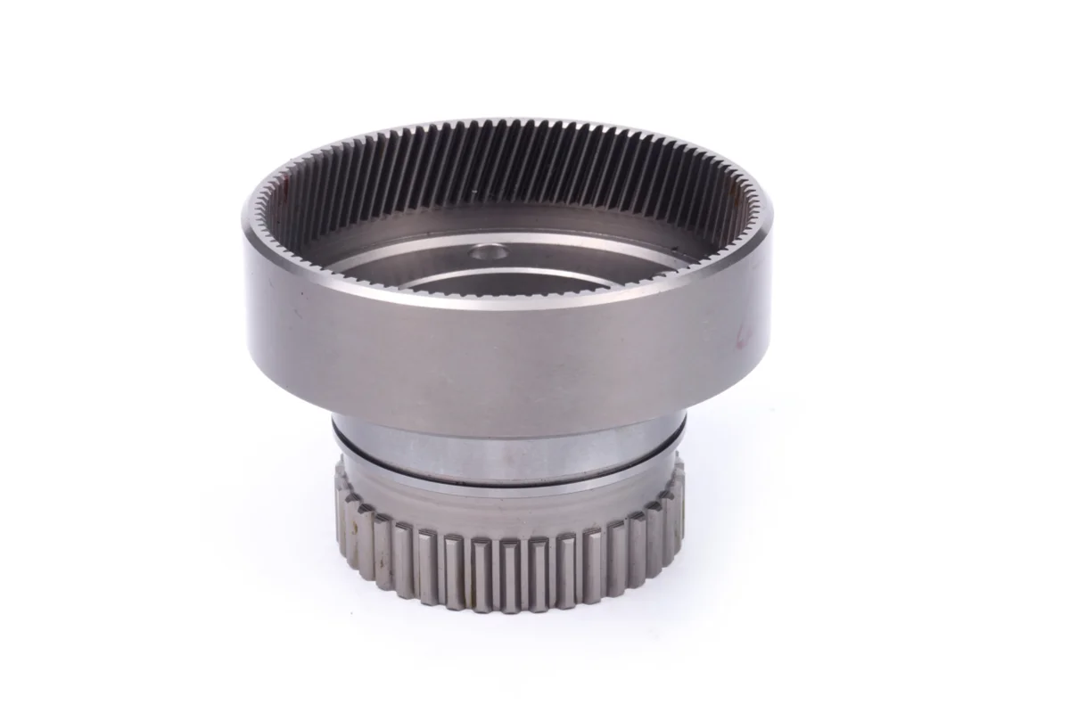
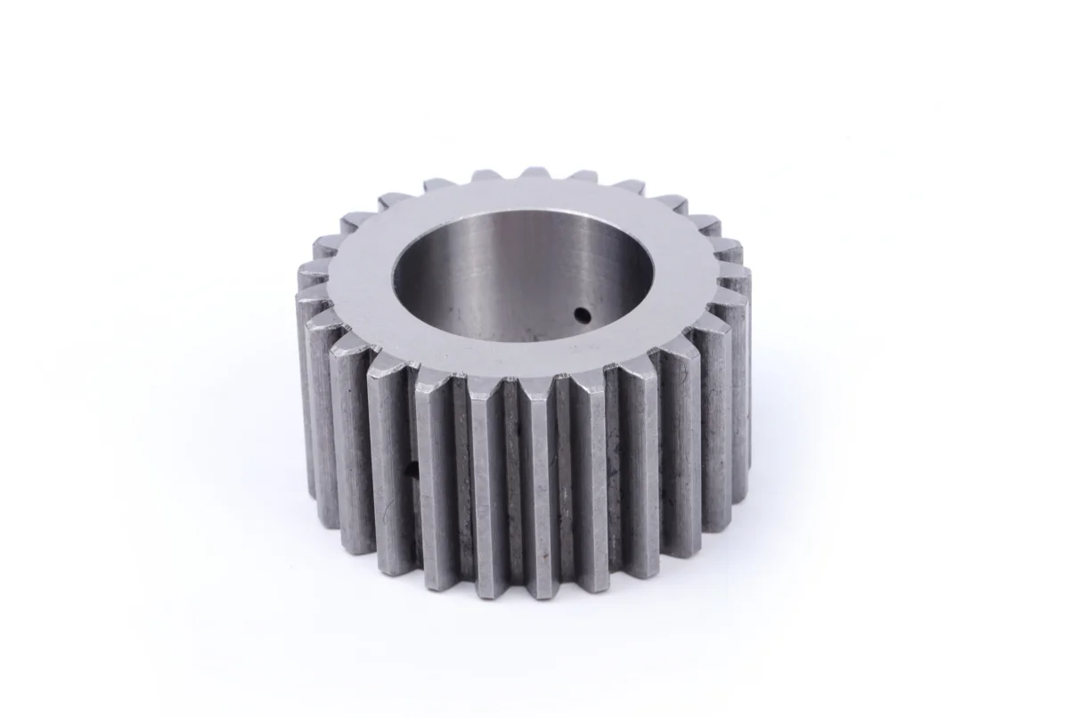
1. Definition and Mathematical Logic of Gear Module
The gear module is a globally unified dimensional parameter with a standard unit of
millimeters (mm). It is technically defined as the ratio of a gear’s reference pitch
diameter to its number of teeth, following the core formula:m=d/z. It can also be
derived from pitch geometry: m=p/π.
The reference pitch circle serves as the exclusive datum for standard gear meshing.
On this benchmark circle, the arc tooth thickness is equal to the tooth space width,
enabling stable pure-rolling conjugate meshing. The core engineering value of the
module is converting complex irrational circular dimension calculations into
standardized linear dimensions, laying a solid foundation for standardized gear
design and high-precision CNC mass production.
Essentially, the module is a proportional scaling coefficient for gear teeth. It
never changes the inherent mechanical properties of involute tooth profiles, but
proportionally scales the tooth thickness, tooth height and overall gear structure.
2. Module’s Decisive Influence on Gear Mechanical Performance
With a fixed number of teeth, the module fundamentally defines the mechanical
performance threshold of gears. A larger module delivers thicker tooth roots and
higher structural rigidity, greatly improving resistance to bending fatigue, contact
fatigue and impact loads. Such gears are widely applied in high-torque, heavy-duty
and high-reliability scenarios, including industrial reducers, engineering machinery
and heavy power transmission equipment.
In contrast, small-module gears adopt compact and delicate tooth structures.
Featuring low meshing backlash, high motion repeatability and low operating noise,
they are the optimal solution for high-precision, light-load and silent transmission
scenarios such as servo systems, precision testing instruments and micro intelligent
actuators.
Core engineering principle: A gear’s outer diameter is determined by both module and
tooth count. However, the load capacity, fatigue life and impact resistance of a
single tooth are exclusively determined by the module — a key guideline for
industrial gear parameter optimization.
3. Core Meshing Rule: Mating Gears Must Have Identical Modules
Identical module is the necessary and sufficient condition for stable conjugate
meshing and accurate power transmission. Only paired gears with consistent modules
can achieve perfect matching of pitch, tooth thickness and tooth space, realizing
tangent pure rolling of reference pitch circles and ensuring smooth, jitter-free and
long-term stable power transmission.
Module mismatch inevitably causes tooth profile interference, abnormal meshing
clearance and local stress concentration. During equipment operation, these defects
trigger severe vibration, abnormal tooth surface wear, tooth root fatigue fracture
and even total transmission system failure. Therefore, module consistency is the
primary inspection index for gear selection, pairing, assembly and equipment
acceptance.
4. Standard Module System: Industrial Foundation of Intelligent Manufacturing
To realize universal part interchangeability, standardized tooling application and
low-cost mass production, ISO and national mechanical specifications have
established a complete standard module series, divided into preferred series and
auxiliary series. Non-standard customized modules are prohibited in industrial batch
manufacturing to avoid extra processing costs and component compatibility risks.
The standard module system unifies the dimensional specifications of spur gears,
helical gears, bevel gears, gear racks and other mainstream transmission components.
It supports cross-manufacturer and cross-equipment universal matching, improves the
generalization rate of mechanical parts, reduces processing, assembly and
after-sales maintenance costs, and fully adapts to the standardized and modular
production mode of modern intelligent manufacturing.
5. Engineering Design and Practical Application Value
In transmission system R&D, the module acts as the initial datum for all gear
parameter calculations. Once the core module is confirmed, a full set of key
parameters including addendum diameter, dedendum diameter, center distance and root
fillet can be accurately derived, covering the entire workflow of 3D modeling,
finite element simulation, CNC machining and precision inspection.
Scientific module selection is the core of transmission system performance
optimization. Large modules are adopted for heavy-load working conditions to improve
structural safety margin and equipment fatigue life. Small modules are applied in
high-precision silent transmission scenarios to reduce meshing backlash and enhance
positioning accuracy. Standard preferred modules are selected for general industrial
equipment to balance structural performance, processing cost and component
interchangeability. Module selection directly determines the overall reliability,
precision and economy of mechanical transmission systems.
Conclusion
As a core theoretical and engineering parameter, the gear module bridges theoretical design, process manufacturing and on-site engineering application. It quantifies the geometric scale and mechanical performance limits of gear teeth and standardizes industrial transmission component specifications. Mastering the underlying logic of gear modules is essential for optimizing transmission structures, solving practical transmission faults and upgrading high-precision mechanical equipment.